- 您现在的位置:买卖IC网 > Sheet目录985 > IRPLLED1 (International Rectifier)BOARD EVALUATION FOR IRS2540PBF
�� �
�
�IRS254(0,1)(S)PbF�
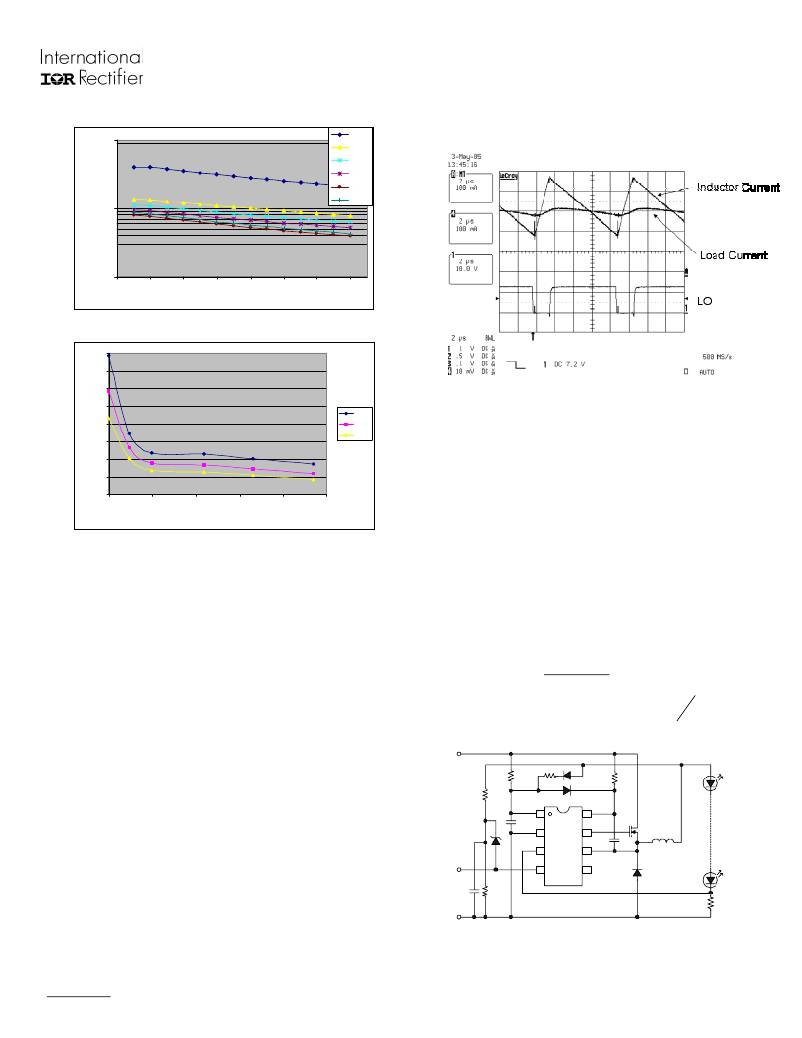
�from� the� output� needs� to� be� implemented,� as� seen� in�
�1000�
�0uF�
�4.7uF�
�Fig.� 16.�
�10uF�
�22uF�
�33uF�
�47uF�
�100�
�10�
�30�
�50�
�70�
�90�
�110�
�130�
�150�
�170�
�Vin� (V)�
�Fig.� 13� I� out� =� 350� mA,� V� out� =� 16.8� V,� L� =� 470� μ� H�
�400�
�350�
�300�
�250�
�200�
�40V�
�100V�
�Fig.� 15� I� out� =� 350� mA,� V� in� =� 100� V,� V� out� =� 16.85� V,� L� =� 470� μ� H,�
�C� out� =� 33� μ� F�
�150�
�100�
�50�
�160V�
�The� resistance� between� V� BUS� and� V� CC� supply� should�
�be� large� enough� to� minimize� the� current� sourced�
�directly� from� the� input� voltage� line;� value� should� be�
�on� the� order� of� hundreds� of� k� ?� .� Through� the� supply�
�0�
�0�
�10�
�20� 30�
�Capacitance� (uF)�
�40�
�50�
�resistor,� a� current� will� flow� to� charge� the� V� CC�
�capacitor.� Once� the� capacitor� is� charged� up� to� the�
�Fig.� 14� I� out� =� 350� mA,� V� out� =� 16.8� V,� L� =� 470� μ� H�
�The� addition� of� the� C� OUT� increases� the� amount� of�
�energy� that� can� be� stored� in� the� output� stage,� which�
�also� means� it� can� supply� current� for� an� increased�
�period� of� time.� Therefore� by� slowing� down� the� di/dt�
�transients� in� the� load,� the� frequency� is� effectively�
�V� CCUV+� threshold,� the� IRS254(0,1)� enters� the� micro�
�start-up� regime� and� begins� to� operate,� activating� the�
�LO� and� HO� outputs.� After� the� first� few� cycles� of�
�switching,� the� resistor� connected� between� the� output�
�and� V� CC� will� take� over� and� source� all� necessary�
�current� for� the� IC.� The� resistor� connecting� the�
�output� to� the� supply� should� be� carefully� designed�
�according� to� its� power� rating.�
�V� out� ?� 15� .� 6� V�
�decreased.�
�With� the� C� OUT� capacitor,� the� inductor� current� is� no�
�longer� identical� to� that� seen� in� the� load.� The�
�inductor� current� will� still� have� a� perfectly� triangular�
�shape,� where� as� the� load� will� see� the� same� basic�
�RS� 2� =�
�10� mA�
�P� RS� 2� =� (� 10� mA� )� 2� RS� 2� ≤�
�Icc� ≈� 10� mA�
�P� RS� 2� _� Rated�
�2�
�trend� in� the� current,� but� all� sharp� corners� will� be�
�rounded� with� all� peaks� significantly� reduced,� as� can�
�be� seen� in� Fig.� 15�
�VBUS�
�VCC� Supply�
�VCC�
�1�
�8�
�VB�
�Since� the� IRS245(0,1)� is� rated� for� 200� V� (or� 600� V),�
�V� BUS� can� reach� values� of� this� magnitude.� If� only� a�
�supply� resistor� to� V� BUS� is� used,� it� will� experience�
�extremely� high� power� losses.� For� higher� voltage�
�ENN�
�COM�
�IFB�
�ENN�
�2�
�3�
�4�
�7�
�6�
�5�
�HO�
�VS�
�LO�
�applications� an� alternate� V� CC� supply� scheme� utilizing�
�the� micro-power� start-up� and� a� resistor� feed-back�
�COM�
�Fig.� 16� Alternate� Supply� Diagram�
�www.irf.com�
�Page� 11�
�发布紧急采购,3分钟左右您将得到回复。
相关PDF资料
ISDCB824
CABLE RIBBON 24"
ISL29000IROZ-EVALZ
EVALUATION BOARD FOR ISL29000
ISL29001IROZ-EVALZ
EVALUATION BOARD FOR ISL29001
ISL29002IROZ-EVALZ
EVALUATION BOARD FOR ISL29002
ISL29003IROZ-EVALZ
EVALUATION BOARD FOR ISL29003
ISL29008IROZ-EVALZ
EVALUATION BOARD FOR ISL29008
ISL29009IROZ-EVALZ
EVALUATION BOARD FOR ISL29009
ISL29010IROZ-EVALZ
EVALUATION BOARD FOR ISL29010
相关代理商/技术参数
IRPLLED1A
功能描述:电源管理IC开发工具 Hi-Vlt DC-DC Buck Cnvr HBLED Cur Cntrl RoHS:否 制造商:Maxim Integrated 产品:Evaluation Kits 类型:Battery Management 工具用于评估:MAX17710GB 输入电压: 输出电压:1.8 V
IRPLLED5
制造商:International Rectifier 功能描述:
IRPLLED7
功能描述:IC MOSFET DRIVER RoHS:否 类别:集成电路 (IC) >> PMIC - MOSFET,电桥驱动器 - 外部开关 系列:* 标准包装:95 系列:- 配置:半桥 输入类型:PWM 延迟时间:25ns 电流 - 峰:1.6A 配置数:1 输出数:2 高端电压 - 最大(自引导启动):118V 电源电压:9 V ~ 14 V 工作温度:-40°C ~ 125°C 安装类型:表面贴装 封装/外壳:8-SOIC(0.154",3.90mm 宽) 供应商设备封装:8-SOIC 包装:管件 产品目录页面:1282 (CN2011-ZH PDF) 其它名称:*LM5104M*LM5104M/NOPBLM5104M
IRPLLNR1
制造商:未知厂家 制造商全称:未知厂家 功能描述:
IRPLLNR2E
功能描述:KIT BALLAST LINEAR INT 230VAC RoHS:否 类别:编程器,开发系统 >> 过时/停产零件编号 系列:- 标准包装:1 系列:- 类型:MCU 适用于相关产品:Freescale MC68HC908LJ/LK(80-QFP ZIF 插口) 所含物品:面板、缆线、软件、数据表和用户手册 其它名称:520-1035
IRPLLNR2U
功能描述:BALLAST 32W/T8 120V AC IR21571 RoHS:否 类别:编程器,开发系统 >> 过时/停产零件编号 系列:- 标准包装:1 系列:- 类型:MCU 适用于相关产品:Freescale MC68HC908LJ/LK(80-QFP ZIF 插口) 所含物品:面板、缆线、软件、数据表和用户手册 其它名称:520-1035
IRPLLNR3
制造商:IRF 制造商全称:International Rectifier 功能描述:Universal Input Linear Fluorescent Ballast using the IR2167
IRPLLNR4
功能描述:BALLAST UNIV INP FLUOR IR2166 RoHS:否 类别:编程器,开发系统 >> 过时/停产零件编号 系列:- 标准包装:1 系列:- 类型:MCU 适用于相关产品:Freescale MC68HC908LJ/LK(80-QFP ZIF 插口) 所含物品:面板、缆线、软件、数据表和用户手册 其它名称:520-1035